MEMS Optical Switches
Dual 1×2 MEMS Switch(Module)
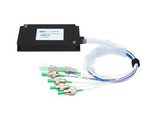
Dual 1x2MEMS Switch(Module) RD-MS-Dual-1×2-PM-M-780-90-10-FA-TTL PM(Polarization-maintaining) Dual 1X2 MEMS Optical Swith,PM PM780,0.9mm loose tube Fiber, FC/APC,TTL Control connection, 90x55x12mm Applications Fiber Optic Sensing Systems: Optical path switchin
Communication Products
Product Overview
Dual 1x2MEMS Switch(Module)
RD-MS-Dual-1×2-PM-M-780-90-10-FA-TTL
PM(Polarization-maintaining) Dual 1X2 MEMS Optical Swith,PM PM780,0.9mm loose
tubeFiber, FC/APC,TTL Control connection, 90x55x12mm
Applications
- Fiber Optic Sensing Systems: Optical path switching and monitoring for FBG fiber grating sensor networks
- Precision Optical Measurement: Polarization-sensitive optical testing and metrology equipment
- Laser Scanning Microscopy: Fast routing and switching of multi-channel laser sources
- Optical Communication Networks: Optical line protection, OADM, and ROADM applications
- Spectral Analysis: Optical path selection and signal distribution for multi-channel spectrometers
- Quantum Optics Experiments: Precise control and switching of polarization-maintaining optical paths
Environmental Conditions
| Parameters | Unit | Min | Max |
| Storage Temperature | ℃ | -40 | 85 |
| Operating Relative Humidity | %RH | 5 | 95 |
| Operating Temperature | ℃ | -5 | 70 |
| ESD Level (HBM) | V | 500 | |
| Max Power Handling | mw | 500 |
Optical Specifications
| Parameters | Unit | Specification |
| Channels | CH | Dual 1×2 |
| Testing Wavelength | nm | 780 |
| Insertion Loss | dB | ≤2.0(with connector) |
| Return Loss | dB | ≥50 |
| extinction ratio | dB | ≥16dB |
| Repeatability | dB | 0.03dB Max |
| Crosstalk | dB | ≥50 |
| PDL | dB | ≤0.15 |
| TDL | dB | ≤0.3 |
| Response Time | ms | ≤20 |
| Durability | Cycle | ≥1×10⁹ |
| Drive Voltage(Max) | V | 5~12 |
| Control Type |
TTL(Parallel /Serial Port Compatibility) The two switches are controlled on the same channel |
|
Notes:
[if !supportLists]1.[endif]The loss is based on the test results at 23℃.
[if !supportLists]2.[endif]Repeatability is defined after 100 cycles.
Electronic Requirement
Pin Definition:
| Pin number |
Pin Assignment |
Signal Type | Description |
| 1 | D0 | Input | Data bit (D0) (low-order) |
| 2 | D5 | Input | Data bit (D5) |
| 3 | VCC | Power | Power Supply (DC 5V,1.0A) |
| 4 | D7 | Input | Data bit (D7) (high-order) |
| 5 | D6 | Input | Data bit (D6) |
| 6 | GND | Power | GND |
| 7 | D4 | Input | Data bit (D4) |
| 8 | D1 | Input | Data bit (D1) |
| 9 | TXD | Output | Data Transmit (TTL Level) |
| 10 | RXD | Input | Data Receive (TTL Level) |
| 11 | D2 | Input | Data bit (D2) |
| 12 | D3 | Input | Data bit (D3) |
| 13 | /BUSY | Output |
Low level means ready to reset orreceiving data |
| 14 | /ALARM | Output | High level means running error |
| 15 | /STROBE | Input | Falling edge execution data bit |
| 16 | /RESET | Input | Low level reset to channel 0 |
Note: Molex 87833-1620 is used for the electrical interfaces of this modules and it is recommended to use Molex 87568-1694 for customer connectors.
UART program control instruction description
This module can receive control signals through the UART interface to enable automated measurements or real-time monitoring.
(2) Please use capital letters.
(3) In practical operation, the angle brackets “<” and “>” are used as the start and end delimiters respectively.
(4). Instruction error returns <ER>.
Program Control Instruction Set
| Order | Describe | Example |
| <RESET> | Restart module | Successful return: <RESET_OK> |
| <RESTORE> | Reset | Successful return: <RESET_OK> |
| <INFO_Magnet> | Query module information |
Return successfully: <MEMS-Dual-1X8_VER1.00_ SN01234567890_08.04.00051> Indicates MEMS-Dual-1X18 module, version 1.00, SN number 01234567890, product number 08.04.00051; |
| <BAUD_x> |
Set or query the serial port baud rate 1.x is 1~9, indicating baud rate 2400, 4800, 9600, 14400, 19200, 38400, 56000, 57600, 115200 respectively Successful return: <BAUD_x_OK> 2. Send <BAUD_Magnet> to query the baud rate |
Send: <BAUD_5> Successful return: <BAUD_5_OK> Set the device serial port baud rate to 19200 The configuration will take effect after saving and rebooting! |
| <OSW_M_x> |
Working mode selection x: Values 0, 1, Magnet, 0 indicates data bit control switching, 1 indicates UART control switching, Magnet indicates query working mode; Successful return: <OSW_M_x_OK> |
Send: <OSW_M_1> Successful return: <OSW_M_1_OK> Indicates that the module is set to UART control switching; Send: <OSW_M_Magnet> Successful return: <OSW_M_1> Indicates that the module is UART controlled switching; |
| <OSW_01_SW_xxx> |
Set current channel xxx: The value is 000~256, 000 means 0 channel, 256 means 256 channel; Successful return: <OSW_01_SW_xxx_OK> Note: In data bit control switching mode, Send: <OSW_01_SW_xxx> Return: <OSW_M_ER> |
Send: <OSW_01_SW_002> Successful return: <OSW_01_SW_002_OK> Indicates switching to channel 2; |
| <OSW_A_Magnet> |
Query channel status Successful return: <OSW_A_Optical switch channel> |
Return: <OSW_A_001> Indicates that the optical switch is 1 channel; |
| <SAVE_ALL> |
Save configuration Successful return: <SAVE_ALL_OK> |
Save the configuration, such as saving the channel status. |
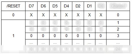
Data bit switching logic table
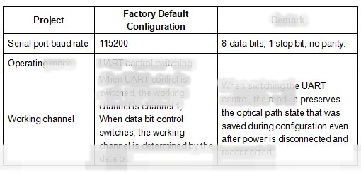
Factory default configuration
PCBA: D3-1 V56
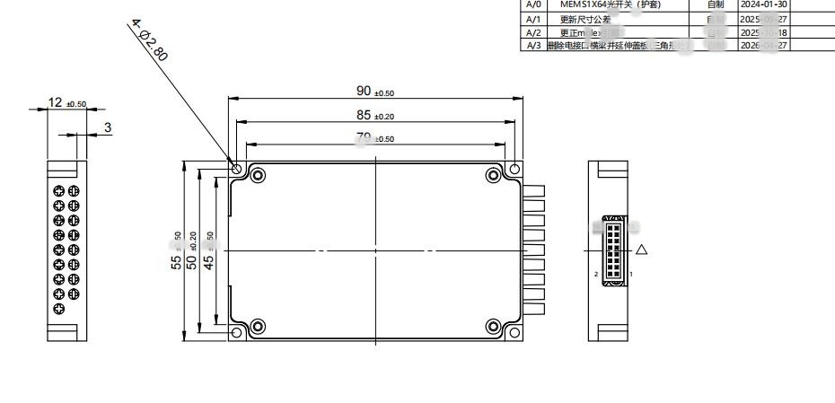
Mechanical Requirement(Units:mm)
Pigtail/Connector Requirement
| Parameters | Specification |
| Fiber Type | PM780,0.9mm loose tube |
| Fiber Length/Tolerance | 1+/-0.05m(without connector) |
| Connector | FC/APC |
| Channel markPM780,0.9mm loose tube |
White number tube with black font, Input–COM1,COM2 Output– OUT1-1,OUT1-2,OUT2-1,OUT2-2 |
Need a customized telecom solution?
Send your target application, quantity and technical requirements. Our team will prepare a suitable product plan.