Mechanical Optical Switches
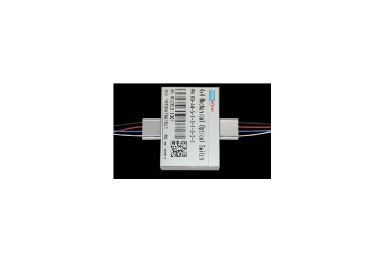
4×4 Mechanical Optical Switch
4x4 Mechanical Optical Switch The 4x4 Mechanical Fiber Optical switch connects optical channels by directing or blocking an incoming optical signal into the output fiber. This is achieved using a patent pending opto-mechanical configuration and activated via a
Communication Products
Product Overview
4×4 Mechanical Optical Switch
The 4×4 Mechanical Fiber Optical switch connects optical channels by directing or blocking an incoming optical signal into the output fiber. This is achieved using a patent pending opto-mechanical configuration and activated via an electrical control signal. A latching version preserves the selected optical path after the drive signal has been removed, while the non-latching versions default to either the open or closed state when power is removed. The switch has integrated electrical position sensors. The new material based advanced design significantly reduces moving part position sensitivity, offering unprecedented high stability as well as unmatched low cost
Specifications
|
Operating Wavelength |
1260~1620nm(SM) 850nm(MM) |
Insertion Loss |
≤1.2dB |
|
Wavelength Dependent Loss |
≤0.4dB |
Polarization Dependent Loss |
≤0.05dB |
|
Temperature Dependent Loss |
≤0.20dB |
Return Loss |
SM≥50dB MM≥30dB |
|
Cross Talk |
SM≥55dB MM≥35dB |
Switch Time |
≤8ms |
|
Repeatability |
≤±0.02dB |
Durability |
≥107times |
|
Operating Voltage |
3 or 5V |
Switch Type |
Non-Latching/Latching |
|
Operating Temperature |
-20~+70℃ |
Storage Temperature |
-40~+85℃ |
|
Optical Power |
≤500mW |
Dimension |
52.7L×37.2.0W×10.0H mm |
Pin Configurations
|
Type |
State |
Electric Drive |
State Sensor |
||||||
|
4×4 |
Pin 1 |
Pin5 |
Pin6 |
Pin10 |
Pin 2-3 |
Pin3-4 |
Pin7-8 |
Pin 8-9 |
|
|
Latching |
0 |
— |
— |
GND |
V+ |
Close |
Open |
Open |
Close |
|
1 |
V+ |
GND |
— |
— |
Open |
Close |
Close |
Open |
|
|
Non-Latching |
0 |
— |
— |
— |
— |
Close |
Open |
Open |
Close |
|
1 |
V+ |
— |
— |
GND |
Open |
Close |
Close |
Open |
|
|
NO. |
Optical Route |
Relay |
|||||
|
1 |
2 |
3 |
4 |
5 |
6 |
||
|
1 |
A-1、B-2、C-3、D-4 |
1 |
1 |
1 |
1 |
1 |
1 |
|
2 |
A-1、B-2、C-4、D-3 |
1 |
1 |
1 |
1 |
1 |
0 |
|
3 |
A-1、B-3、C-2、D-4 |
1 |
1 |
1 |
1 |
0 |
1 |
|
4 |
A-1、B-3、C-4、D-2 |
1 |
1 |
1 |
0 |
0 |
1 |
|
5 |
A-1、B-4、C-2、D-3 |
1 |
1 |
1 |
1 |
0 |
0 |
|
6 |
A-1、B-4、C-3、D-2 |
1 |
1 |
1 |
0 |
0 |
0 |
|
7 |
A-2、B-1、C-3、D-4 |
1 |
1 |
0 |
1 |
1 |
1 |
|
8 |
A-2、B-1、C-4、D-3 |
1 |
1 |
0 |
1 |
1 |
0 |
|
9 |
A-2、B-3、C-1、D-4 |
1 |
1 |
0 |
1 |
0 |
1 |
|
10 |
A-2、B-3、C-4、D-1 |
1 |
1 |
0 |
0 |
0 |
1 |
|
11 |
A-2、B-4、C-1、D-3 |
1 |
1 |
0 |
1 |
0 |
0 |
|
12 |
A-2、B-4、C-3、D-1 |
1 |
1 |
0 |
0 |
0 |
0 |
|
13 |
A-3、B-1、C-2、D-4 |
1 |
0 |
1 |
1 |
0 |
1 |
|
14 |
A-3、B-1、C-4、D-2 |
1 |
0 |
1 |
0 |
0 |
1 |
|
15 |
A-3、B-2、C-1、D-4 |
1 |
0 |
0 |
1 |
0 |
1 |
|
16 |
A-3、B-2、C-4、D-1 |
1 |
0 |
0 |
0 |
0 |
1 |
|
17 |
A-3、B-4、C-1、D-2 |
0 |
0 |
1 |
0 |
0 |
1 |
|
18 |
A-3、B-4、C-2、D-1 |
0 |
0 |
0 |
0 |
0 |
1 |
|
19 |
A-4、B-1、C-2、D-3 |
1 |
0 |
1 |
1 |
0 |
0 |
|
20 |
A-4、B-1、C-3、D-2 |
1 |
0 |
1 |
0 |
0 |
0 |
|
21 |
A-4、B-2、C-1、D-3 |
1 |
0 |
0 |
1 |
0 |
0 |
|
22 |
A-4、B-2、C-3、D-1 |
1 |
0 |
0 |
0 |
0 |
0 |
|
23 |
A-4、B-3、C-1、D-2 |
0 |
0 |
1 |
0 |
0 |
0 |
|
24 |
A-4、B-3、C-2、D-1 |
0 |
0 |
0 |
0 |
0 |
0 |
Mechanical Dimensions (Unit:mm)
Optical Route
Ordering Information
|
RD-FSW |
-4×4- |
-Wavelength- |
-Switch Type- |
-Voltage- |
-Fiber Type- |
-Package- |
-Fiberlength- |
-Connector- |
|
1060=1 C+L=2 1310=3 1410=4 1550=5 650=6 780=7 1260-1610=A 1310/1550=9 850=8 Special=0 |
Latching=1 Non-latching=2 Special=0 |
3V=3 5V=5 Special=0 |
SM28=1 50/125=5 62.5/125=6 Special=0 |
Bare fiber=1 900um tube=3 Special=0 |
0.25m=1 0.5m=2 1.0m=3 Special=0 |
None=1 FC/PC=2 FC/APC=3 SC/PC=4 SC/APC=5 ST/PC=6 LC/PC=7 Duplex LC=8 Special=0 |
Need a customized telecom solution?
Send your target application, quantity and technical requirements. Our team will prepare a suitable product plan.