MEMS Optical Switches
1X4 PM MEMS Optical Switch
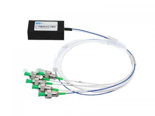
PM (Polarization-maintaining) MOSW-1X4-15-PM-09-05-03A-M1 1X4 PM MEMS optical switch,module packaging,5V driving voltage,1550nm, Corning PM1550 fiber 0.9mm loose tube,0.5m length,input output FC/APC connector 54.1*13.7*24.7mm MEMS 1xN optical switch is based o
Communication Products
Product Overview
PM (Polarization-maintaining) MOSW-1X4-15-PM-09-05-03A-M1
1X4 PM MEMS optical switch,module packaging,5V driving voltage,1550nm,
CorningPM1550 fiber 0.9mm loose tube,0.5m length,input output FC/APC
connector 54.1*13.7*24.7mm
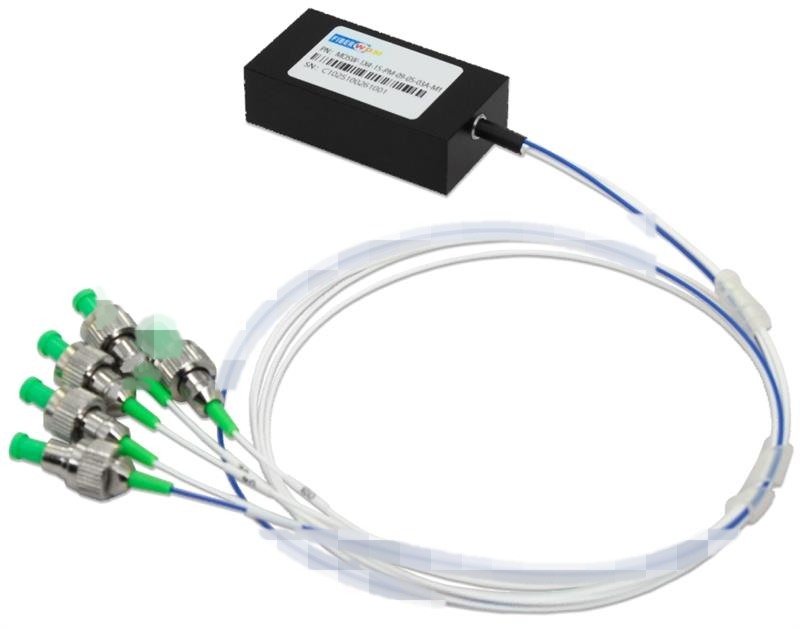
MEMS 1xN optical switch is based on micro-electro-mechanical system technology. It allows channel selection between an input fiber and up to N output fibers by rotating the MEMS mirror.
The switch is bi-directional and can also be used as a Nx1 selector switch. The optical switch offers highly reliable, durable, long-life operation in a compact package.
Features
- Proven MEMS durability and reliability
- Compact Form Factor
- Fast switching time
- Qualified to Telcordia GR-1073-CORE and RoHS
- UART/TTL or UART/RS232 control interface
Applications
- Optical network routing
- Resource sharing in test & measurement applications
- Optical network protection and restoration
Optical Performance Specifications
| Optical Parameters | Unit | Specificatios | ||
| Min | Type | Max | ||
| Operating Wavelength | nm | 1260 | 1310&1550 | 1650 |
| Test Wavelength | nm | 1310\1550 | ||
| Number of channels | — | 4 | ||
| Insertion Loss1,3, (MAX) | dB | 1.0 | 1.3 | |
| PER | dB | 18 | ||
| Polarization Dependent Loss | dB | 0.15 | ||
| Return Loss | dB | 45 | 50 | |
| Crosstalk | dB | 50 | ||
| TDL | dB | 0.3 | ||
| WDL | dB | 0.3 | ||
| Repeatability2 | dB | 0.03 | ||
| Switch Time (rise, fall) | ms | 10 | 15 | |
| Durability | times | 10^9 | ||
| Operating Voltage | V | 5.0 | ||
| /Power Handling | mw | 500 | ||
| Environmental Properties | Unit | Specificatios | ||
| Operating Temperature | °C | -5 ~ 75 | ||
| Storage Temperature | °C | -40 ~ 85 | ||
| Operation Humidity | %RH | 5 to 95%RH | ||
| Other Parameters | Unit | Specificatios | ||
| Connector Type | — | FC/APC | ||
| Fiber Type | — | Corning PM1550 fiber | ||
| Fiber Packge | — | 900um loose tube | ||
| Fiber Length | M | 0.5+0.1/-0 | ||
| Pigtail Color | Input | Red | ||
| Output | White | |||
Note:1.IL is measured at CWL, 23℃.
2.Repeatability is defined after 100 cycles.
3. Exculding connectors, and add 0.3dB IL for a pair of connectors.
4. IL is for single-band. Dual-band adds 0.3 dB.
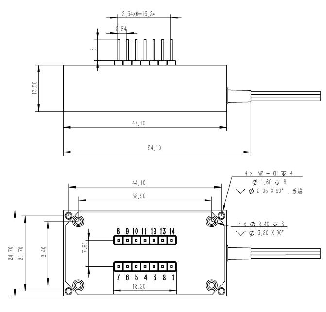
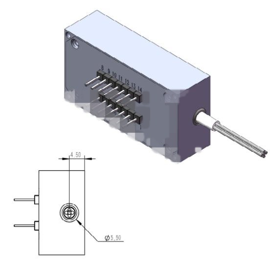
Dimensions Diagram
M1:For M1X4
Optical Route
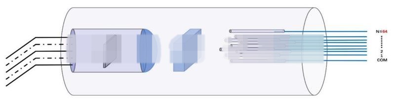
The mems optical 1×128 switch is a non-locking product. When the voltage is removed, the mirror returns to the initial position and the input is uncoupled to any output channel. The principle of optical path switching is shown in figure below.
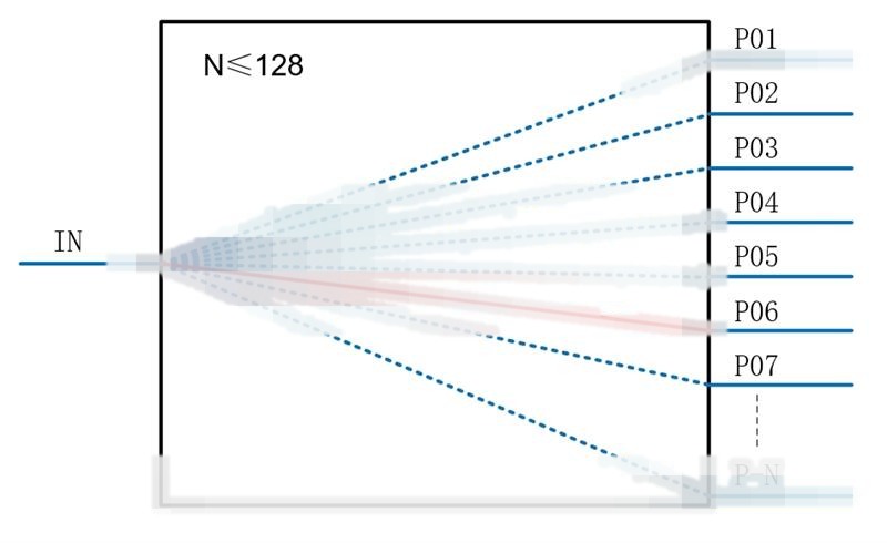 1×N Multichannel Optical Switch System
Electronic Requirement
Pin Definition
| Pin | Type | Description | Input/output | Remark |
| 1 | D0 | Parallel Data Interface 0 | Input | TTL(H level default) |
| 2 | D3 | Parallel Data Interface 3 | Input | TTL(H level default) |
| 3 | D4 | Parallel Data Interface 4 | Input | TTL(H level default) |
| 4 | VIN | Power Input | Input | DC 5V~12V |
| 5 | GND | GND | Input | |
| 6 | D5 | Parallel Data Interface 5 | Input | TTL(H level default) |
| 7 | D2 | Parallel Data Interface 2 | Input | TTL(H level default) |
| 8 | TX | Serial port send | Output | TTL |
| 9 | RX | Serial port receive | Input | TTL |
| 10 | D1 | Parallel Data Interface 1 | Input | TTL |
| 11 | BUSY |
Busy signal, high levelindicates busy |
Output | TTL |
| 12 | ALARM | Alarm signal, high level indicates high temperature or Initial Abnormal | Output | TTL |
| 13 | STROBE | Signal of parallel port selection,falling edge is effective | Input | TTL(H level default) |
| 14 | RESET | Hardware reset, low level effective | Input | TTL |
Firmware Definition
[if !supportLists]1)[endif]UART parameter 115200,8,1,N
[if !supportLists]2)[endif]All sending instructions end with <cr>, All response instructions end with <cr><lf>content<cr><lf>.
(Enter <cr> with ‘\r’, ASCII code is 13, hexadecimal code is 0x0D)
(The newline <lf> is represented by the ‘\n’, the ASCII code is 10, and the hexadecimal code is 0x0A)
Channel switching instruction
| Instruction | *SW |
| Parameter | *SWABC,000 for status of power off,001 for channel 1 |
| Return data | CHAN:ABC,PCB power off and no data feedback |
|
Examples:*SW + ABC Send data:*SW001<cr> Return data:<cr><lf>OK<cr><lf> |
|
Enquire Product Number
| Instruction | *PN |
| Parameter | None |
| Return data | PN:AB.CD.EFGH |
|
Examples: Send data:*PN<cr> Return data:<cr><lf> AB.CD.EFGH <cr><lf> |
|
Enquire Series Number
| Instruction | *SN |
| Parameter | None |
| Return data | SN: ABCDEFGHIJ |
|
Examples: Send data:*SN<cr> Return data:<cr><lf> ABCDEFGHIJ <cr><lf> |
|
Description of parallel communication interface
The 14PIN module has 6 TTL control pins (D0~D5) and up to 64 channels.
Use TTL to control D0~Dx pins to select the channel TTL, switch channels with falling edges STROBE.
The channel selection definitions are shown in the following table:
|
Channel selection |
D5 | D4 | D3 | D2 | D1 | D0 |
| Channel 1 | 0 | 0 | 0 | 0 | 0 | 0 |
| Channel 2 | 0 | 0 | 0 | 0 | 0 | 1 |
| Channel 3 | 0 | 0 | 0 | 0 | 1 | 0 |
| … | ||||||
| Channel 63 | 1 | 1 | 1 | 1 | 1 | 0 |
| Channel 64 | 1 | 1 | 1 | 1 | 1 | 1 |
Firmware Version:C4-1,V01
Odering Information
| Part No. | Specification |
| MOSW-1X4-15-PM-09-05-03A-M1 | 1X4 PM MEMS optical switch,module packaging,5V driving voltage,1550nm,Corning PM1550 fiber 0.9mm loose tube,0.5m length,input output FC/APC connector 54.1*13.7*24.7mm |
FAQ:
Q: Does the product support bidirectional communicationMagnet
A: Yes, the switch features a bidirectional design. It can be used as a 1×4 optical switch and also in reverse as a 4×1 selector switch.
Q: How many channels does the parallel control interface support at mostMagnet
A: Through a total of 6 TTL control pins (D0~D5), it can support the selection of up to 64 channels (Channels 1~64 correspond to different pin level combinations).
Need a customized telecom solution?
Send your target application, quantity and technical requirements. Our team will prepare a suitable product plan.